Front Suspension Rebuild - Part 3 - 05/28/2017
The never ending suspension rebuild continues...
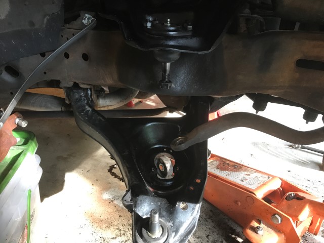
After much sweat, tears, and bruised fingers, the lower control arm is lined up and ready to compress the spring into place. New bushings and old frame give considerably more problems than I would like there to be, fortunately nothing is rusty or rotten.
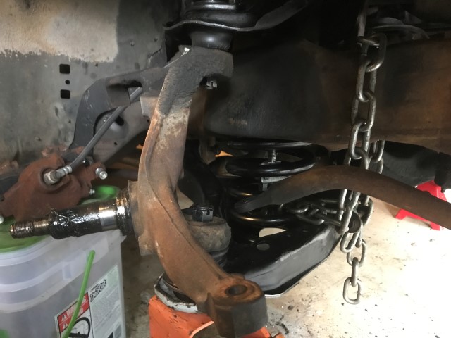
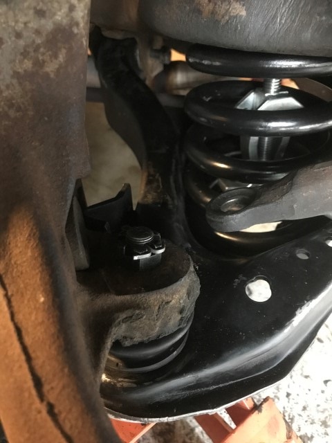
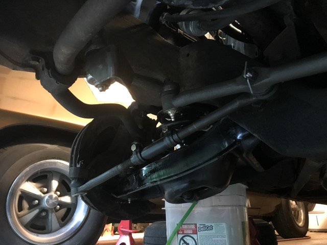
Spring is compressed into place and spindle ("steering knuckle" per GM) is bolted down and not going anywhere. This took multiple steps. It started out with threading my spring compressor down through the frame mount and into position with the spring lifted into place with the jack. The spring lower coil end needs to line up *very* closely with the 2 holes in the previous picture about 1 o'clock in the picture. This is the lower spring pocket and if the spring doesn't go in here, it will rattle and move (per the internet, I find that dubious at best), not to mention it's engineered as a spring to have that spot and compression for this specific car weight with AC. Then put the spring compressor arms 2 or 3 coils from the bottom and tighten it down... A LOT. This is a nerve wracking job as that spring is incredibly strong to support 5000lbs. The chain is placed around the bottom so that if the spring compressor fails or the spring slips out, it won't go anywhere and do any damage to anything that matters (garage floor, me). Once the spring is compressed more than I'm comfortable with, I start lifting the lower control arm into place with the jack under the lower ball joint (furthest spot out, most leverage). As I lift it, the spring will need to be coerced into place, and since the spring is already compressed it will have to be coerced further into the car from where it is now. I use a very large prybar in several places to make this job go extremely slowly and carefully. No sense rushing here. Raise jack, coerce spring, raise jack, coerce spring over and over again until finally it goes *BOOM* and pops right into place, lower coil right in the drain hole pocket. Raise lower control arm continuously without needing to worry about the spring coersion anymore and then put the spindle on the lower ball joint, nut it up, put upper ball joint on top and nut it down (I like to see ball joint extending out of the castle nut like in the photo) and then the jack can be removed. The spring compressor likes to fall off during this process which is part of the big boom, hence the chain. I still can't believe the GM service procedure is to assemble the spindle to the ball joints and lift the lower control arm using a J-tool into the bushing holes on the frame. Everyone says this job is easy and no big deal, but big car stuff of this era is almost similar to 1/2 ton and 3/4 ton truck in stiffness and size, so it definitely requires more oomph than the average GTO or Firebird...
I will say that having to remove the rotor and bearings to get the dust shield off so I could put the spindle on the ball joint stud was VERY annoying, which I discovered after I had everything compressed and ready to go into place. So... that was fun having to take the rotor off on the floor in the driveway while praying the jack wouldn't fail. It didn't so that's good.
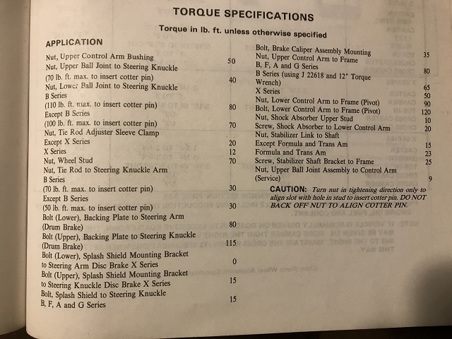
This is important, factory torque specs since most of the new parts have no reference whatsoever to torque specs, namely "do what the factory says" which is why the factory info is important to have.
Upper ball joint torque down (40ft-lbs).
Cotter pins go in. Important thing to remember here is to always tighten over torque spec to get cotter pin in, never back off.
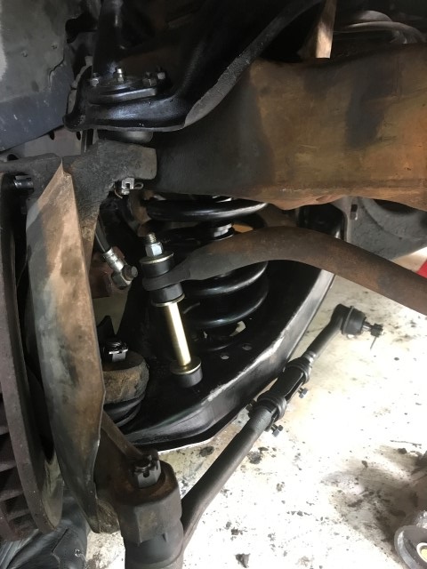
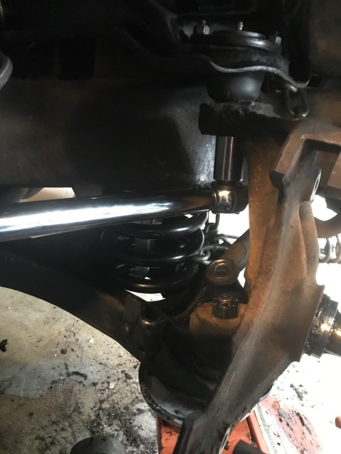
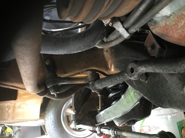
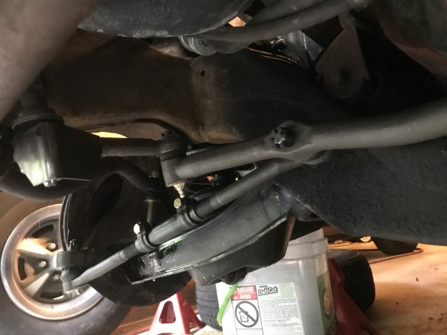
Stabilizer bar end-link installed, tie rod in. Also of note is new shock absorber, I went with load leveling Monroe shocks for the car as they weren't overly expensive and should last a good while. They're also pretty tough and should keep the car from bottoming out too badly.
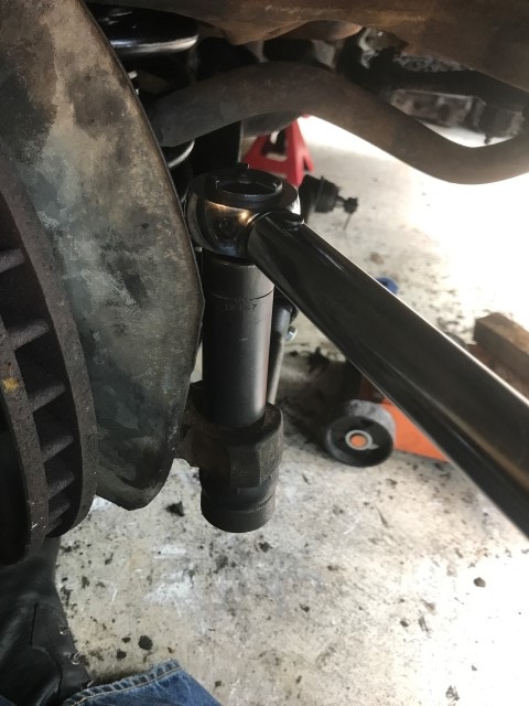
Tie rod is torqued down. That's pretty much it for the driver's side. In the process of putting the dust shield, rotor, and bearings back on, I ended up crushing my index finger and cutting up the tips of 3 fingers. So even with gloves on this is tough\dangerous work. This pair of gloves is going in the trash, I've got holes and nastiness in 2 pairs so far on this job.
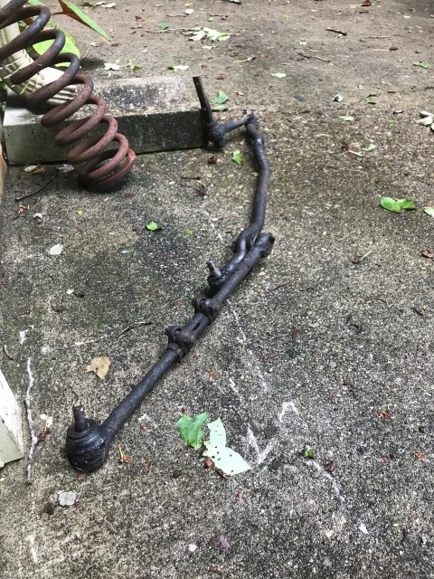
Old center link is pretty much wasted. This was AFTER cleaning it up.
Old idler arm and center link are cleaned up to get cotter pins out to remove nuts and break tapered fittings free.
Center link assembly removed! Took a while as the pitman arm fitting was incredibly greasy so I had to clean it multiple times to keep the puller from slipping off.
New idler arm is installed. Positioning is critical here because apparently you can put it in backwards... the way it's in is correct.
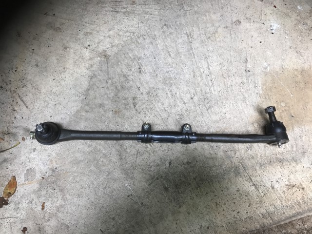
New tie rod assembly made up for the driver's side.
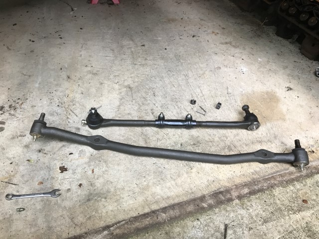
The new center link and tie rod setup together, looks pretty nice (and greasy free!).
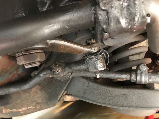
New center link goes in, threaded nut onto center link, and new passenger tie rod assembly is attached and nut threaded on.
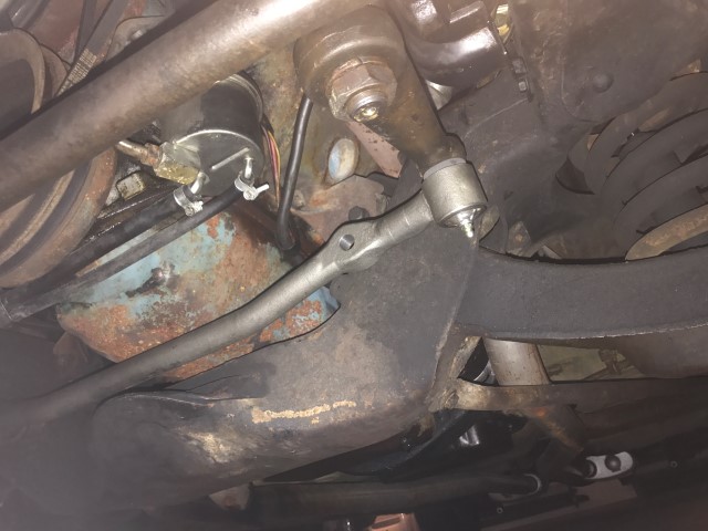
New center link attached to pitman arm.
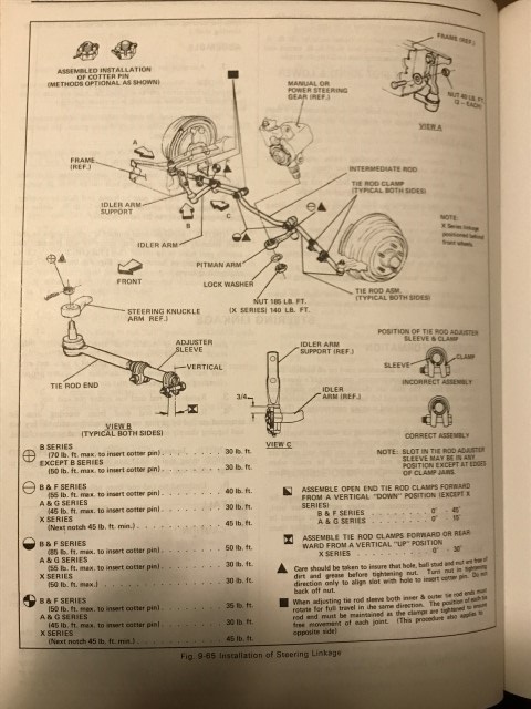
The all important steering connection torque specifications sheet...
Proper torque made, cotter pins installed. Passenger side is done.
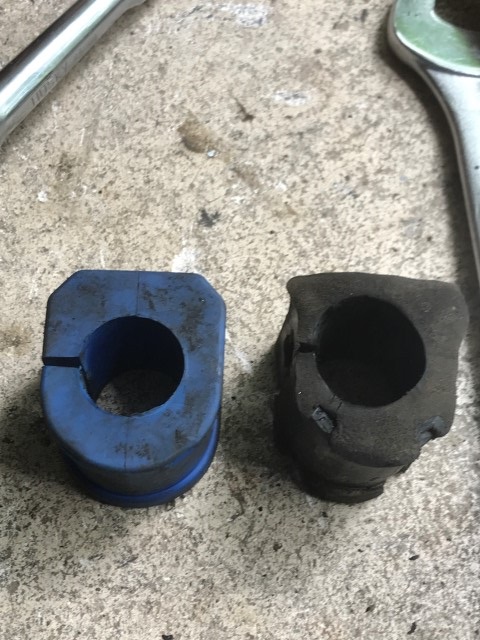
So... aftermarket parts rant. The front sway bar has 2 bushings to hold it on to the frame and assist with steering control\stabilizing (why it's called the "stabilizer bar" in the manuals). Obviously after 45 years and tons of road grime\grease and leaky engines, the rubber fails. No biggie, get new bushings and replace them. Well... Moog (and others) have improved the technology of the rubber used in the last 40 years, so you get modern technology on your car... except that it doesn't exactly fit. It's obvious comparing the 2 that... this isn't exactly going to be an *easy* compression. I fought with it for an hour and still no joy... it's at least 1/4" too tall. I'm sure a he-man kung-fu grip superstar could compress this correctly using his bare hands (or at least some special tool) but I ain't that. So I'm going to end up probably hunting down the Energy Suspension parts that come with a new bracket to take out the guess work. They aren't overly expensive and it's not like the car has a hot date tonight...
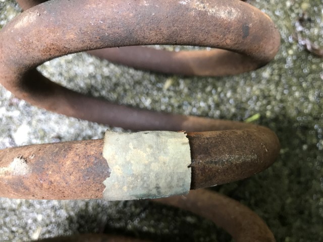
The old factory spring still has its GM parts tag on it: "...8125" is all I can easily make out. Unfortunately that doesn't correspond to a part in the GM books I have.
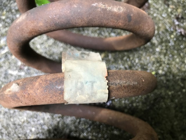
And it definitely says "RT" for the right side of the car. I like little things like this.
Well, not finished but definitely making progress. Need to tear apart the driver's side control arm setup, disassemble, clean, and paint it. Then assemble new bushings and install. After that's done I need to put the wheels back on the car and lower it to ride height and torque all the bushings to their proper level. That should get me close enough to drive to an alignment shop!
Return to 1973 Grand Safari
Last updated May 28th, 2017